PRIMARY FLUID SYSTEM

Discover the right solutions you may need for your dosing pump application.

Ana Sayfa Discover the right solutions you may need for your dosing pump application. WANNER™ Hydra-Cell®  piston diyaframlı pompalar, 170

Primary Fluid Systems began manufacturing systems for local applications in 1991. Since then, it has continued to produce high-quality dosing pump accessories for various industries with its innovative and patented designs.

We provide the best solutions to our customers in many sectors such as water and wastewater treatment, oil and gas, pharmaceuticals, food and beverage.

With over 30 years of industry experience, our valves, which can last more than 15 years in the field, allow us to offer much longer-lasting and more durable products compared to our competitors. Each product makes a difference in the industry thanks to its innovative features.

How Does a Safety Valve Work?

A relief valve is a safety element that reduces pressure and protects equipment by discharging fluid when the pressure in a system exceeds a specified safe level.

PFS Aquguard Diaphragm Manometers

AccuGUARD Pressure Gauges are designed to improve the performance of chemical supply systems. Adding a pressure gauge to any system ensures monitoring and maintenance of optimum pressure levels.
Max. Flow Rate : l/h
Max. Pressure : bar

In stock

PFS Injection Valves

These are spring-loaded valves typically used to separate the pump discharge line from the process line.
Max. Flow Rate : 200 - 630 l/h
Max. Pressure : bar

In stock

PFS Calibration Cylinder

The calibration process for dosing pumps is carried out using equipment called calibration cylinders. Calibration cylinders are made of PVC, polypropylene, and glass materials and have different capacity options ranging from 100 ml to 20,000 ml.
Max. Flow Rate : 100 - 20,000 ml/h
Max. Pressure : bar

In stock

PFS Pulsation Dampers

Pre-filled with nitrogen, models are available with bladder, diaphragm, piston, bellows-type toothed cover, welded body or forged rod.
Max. Flow Rate : l/h
Max. Pressure : 200 bar

In stock

PFS Top Valve Back Pressure Control Valves

The use of a back pressure control valve in the discharge line is critical for ensuring constant pressure throughout the operating period.
Max. Flow Rate : 15-6500 l/h
Max. Pressure : 400 bar

In stock

PFS Top Valve Safety Valves

In some cases where electric motor-driven or solenoid-type dosing pumps have a pressure higher than the line pressure, safety valves (relief valves) are used to protect the line from high pressure and potential chemical leakage damage.
Max. Flow Rate : 15-6500 l/h
Max. Pressure : 400 bar

In stock

How Does a Safety Valve Work?

The working principle is based on the balance of pressure and spring force. When the pressure in the system is below the set pressure value, the spring force keeps the disc closed and the fluid is not discharged. If the pressure exceeds the set pressure level, the pressure force overcomes the spring, the disc lifts and the fluid is discharged. At this time, the pressure starts to drop. When the pressure drops back to a safe level, the spring closes the disc again and the system returns to normal.

What is a Safety Valve (Relief Valve)?

A relief valve is a safety element that reduces pressure and protects equipment by discharging fluid when the pressure in a system exceeds a specified safe level. It is especially used in pressure-generating equipment such as pumps, pressure vessels, pipelines, compressors and hydraulic systems.

It protects the system from explosion, leakage, equipment damage and personnel safety risks.

Why Use It?

A relief valve is vital in the following situations:

Risk

Role of the Relief Valve

Equipment may be damaged if the pressure rises uncontrollably

Discharges excess pressure

Pump dead heading

Protects the pump from overloading

Pressure increase due to thermal expansion

Reduces pressure to a safe level

Sudden pressure surges in the installation

Ensures system safety

Human and environmental safety

Prevents accidents

A pressurized system without a relief valve poses a serious hazard.

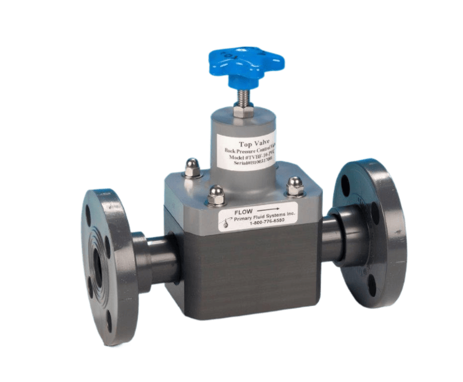
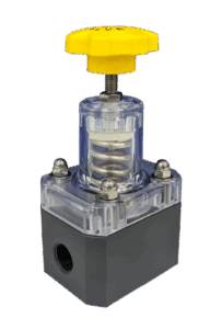
Structure (Basic Components)

A relief valve usually consists of the following parts:

  • Valve body
  • Inlet and outlet connections
  • Piston or disc (part that sits on the valve seat)
  • Spring → Maintains the set pressure
  • Set screw → Determines the operating pressure
  • Cover and guiding system

Thanks to the tight closing of the disc with the spring on the valve seat, there is no flow passage during normal operation.

How Does It Work?

The working principle is based on the balance of pressure and spring force:

  1. When the pressure in the system is below the set pressure value:
    • The spring force keeps the disc closed
    • Fluid is not discharged
  2. If the pressure exceeds the set pressure level:
    • The pressure force overcomes the spring
    • The disc lifts and fluid is discharged
    • Pressure starts to drop
  3. When the pressure drops back to a safe level:
    • The spring closes the disc again
    • The system returns to normal

These processes take place very quickly and provide continuous control.

Relief Valve Types

Type

Usage Feature

Spring-loaded

The most common type, in pumps and hydraulic systems

Pilot-operated

High flow rate and precise pressure control

Thermal relief

Only for thermal expansion pressure

Vacuum relief

Protects against negative pressure

Safety Valve (PSV)

With sudden opening and closing in pressure vessels

Selection Criteria

The following parameters should be considered when selecting a relief valve:

  • Set pressure (safety pressure)
  • Min./Max. operating pressure
  • Fluid type (corrosive, viscous, gas, steam)
  • Discharge flow rate
  • Material selection (SS, bronze, cast iron, PTFE gasket, etc.)
  • Standard requirements such as ATEX, API, ASME